Archive for category rigging

aimConstraints with no up vector

I’m pretty good about looking at the docs for nodes I use in Maya, because often there’s hidden functionality or switches that make nodes behave completely differently, and these things are often not apparent. A good example is on the extendCurve node– there’s a “join” attribute that’s completely hidden, but I found that setting it to zero was the difference between having a useful node and not.

A few weeks ago I discovered, much to my embarrassment, that I had not done my homework on aimConstraints. It turns out that the aimConstraint node’s up vector type can be set to “none”, which converts the aimConstraint into a quaternion-slerp-based orienter. This means that whatever you’ve picked will still aim at the target, but it won’t twist on the aim axis relative to the parent transform.

This is a lot like the SingleChainIK solver, but it has one important benefit: Not being an IK solver. IK solvers / handles in Maya have some very strange and esoteric bugs that don’t show themselves in every situation or even on every show, but when they hit, they hit hard. The more I use Maya, the more I find that skipping an IK handle wherever possible is the Right Thing.

The SingleChain solver is extremely useful for a variety of setups, but one problem I’ve encountered is that the handle itself doesn’t like to be scaled. I had some rigs where if the character were scaled below 0.5 or above 2.0, Maya would freeze for a few seconds and the SC solver would be broken once that number was passed. I fixed the issue by moving the IK handle into a group outside the hierarchy and pointConstraining it to the IK goal object, but the extra work bugged me. With an up-vectorless aimConstraint, I can remove a few extra transforms.

Another interesting node is that the RPSolver behaves exactly the same as both the SCSolver and the up-vectorless aimConstraint if its poleVector attribute is set to (0,0,0), and the solver is operating on a single bone chain. Not sure what use this is, but it’s in there.

How about an example use?
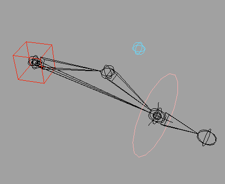

arm with pole chain
( download example .ma )

Adding an SCsolver chain from the shoulder to the wrist (aimed at the wrist control), then using it to move the pole vector around, can often be a very good way to extend the reach of a character’s IK arms without forcing the animator to constantly move the pole vector control. Give it a go– you’ll see what I mean. This setup doesn’t work on legs, depending on the animator, but for arms it’s not bad and with space switching you can still have the standard pole vector placement behind the chest if so desired.

the mortal instruments: city of bones

I’m excited to say that The Mortal Instruments: City of Bones is now in theatres! I worked on the wolves, designing an autorig for their bodies as well as a new type of animal leg rig. The faces and finaling were done by the talented Farrukh “King” Khan.

As an aside, I saw the movie last week with my family and it turned out wonderful, especially when compared to the Twilight series. Here’s hoping it does well!

spline IK overshoots

I’m constantly attempting new setups in rigging. Usually this is out of necessity, such as when current scripted setups don’t behave reliably or deliver the desired result with new models. Other attempts are me exploring things about my setups with which I’m not one hundred percent satisfied. I’ll keep doing research until I find a setup that works as I feel it should in the majority of situations, stably and predictably.

Stretchy Spline IK is something I’ve never liked because of the way its chains overshoot the end of the curve when the spline’s curvature is too great. I’ve never worked in a studio that had its own custom Spline IK solver, where this problem is non-existent, so I research solutions whenever I hit the issues that stretchy splines always bring.

Recently I had a thought about using live sub-curves of a spline (using the Maya subCurve node). I’ve always figured that the overshoots are due to floating point rounding and the fact that measuring a nurbs curve is an inexact science; curves are sub-samples a few thousand times, and the distances between points are summed.

(Before you ask, I use splines because they’re easy and light when you need to be able to lock a chain to a minimum or maximum length, but still allow stretching. I have not found a fast way of doing the same using a nurbs ribbon.)

I wrote a custom node to extract sub-curves by length along the original curve (using MFnNurbsCurve::findParamFromLength), then attached joints to each subCurve with Spline IK. I figured that sub-curves made by length would lock each joint in place, and that somehow this would work around the overshoot issue.

Boy was I wrong.

Turns out the assumption I’ve had for a while– the same assumption I’ve heard from other riggers– was itself incorrect. It’s not that the lengths aren’t being measured accurately enough, but that as the spline curves in on itself, the effective lengths of bones on it should shrink because the bones can’t bend to match. Obvious in hindsight, but it caught me by surprise. It’s like Manhattan Distance: in Euclidean space you may only be two kilometers from that pizzeria you love, but you end up walking three kilometers to get there because Euclidean distance doesn’t take into account the fact that we can’t pass through buildings. (Or: that sewers are winding and not always as easy to traverse as the city streets for your average turtle.)

On the up side I can think of a few good uses for the sub-curve node I made, so the experiment wasn’t a total loss. I also have a few ideas of how to use the curvature of the driving spline to come up with a scale value, meaning I have new experiments to carry out.

The test proved to me again that it never hurts to pull apart an established method in an attempt to do it better. “White belt mind,” a teacher of mine used to say– try to never lose that initial state we all have when we begin something new and are constantly trying to learn.

Tags: , ,

batch wrangling part 2 – Maya 2012 Human IK

The second half of the work I did was to automate the process of moving data around between Motion Builder and Maya, and to make tools for the animators that lightened their loads when it came to exporting and retargeting animations. I was also responsible for a batch conversion pipeline.

On the project there were animations in Motion Builder FBX files that were intended for reuse, which meant loading and retargeting multiple animations across multiple characters. This is a case (if only minimal edits are required) where the HIK system in Maya can be used to blast through conversions and free up animators for other work. Also, as many of the original animations were in single FBX files as Takes and the new decision was to have one file per animation (allowing multiple animators to work on the same character without file collisions in the version repository), the multi-take Motion Builder FBX files would need to be split in batch.

The Maya Human IK system as of Maya 2012 is usable and has a lot of good benefits. Much of what they say works out of the box really does, provided you stick within the system: the ability to retarget animations between characters of differing sizes and joint placements works very well, and the fidelity of those animations stays high. If you rename or reorient bones but still have a Characterization in place for both characters, the transfer will still work out. However, there were also significant downsides:

  • The Motion Builder to Maya one-click scene send did not work as expected 100% of the time. When transferring from Motion Builder to Maya, I often found that while the Characterization would transfer over the rig itself would not be properly connected, and many times did not even come in at the right position in the Maya scene. Baking the keys down to the skeleton, transferring, and regenerating the rig on the Maya side does work. You lose the editability of having less keys, but you get a one-to-one transfer between the two programs this way and the Characterization makes rebuilding and rebaking the keys to the rig a one-click process.

  • On the Maya side you lose a lot of the features you’d expect. For example, the animators complained about not having foot roll controls. Regular Maya constraints don’t behave the same way you’d expect, and adding onto an HIK rig can be trickier than building on top of a regular Maya rig. The strangest thing was that you can’t zero controls. If you want to return to the “stance” pose, you have to change the input to the skeleton, then key the rig at the frame you want to have zero’d, and finally go back to having the rig control the skeleton. Editing curves on the HIK rig can be frustrating, as both the FK and IK objects are used to control the final position of joints and the different Human IK modes for posing and interaction pull at the body parts in different ways; often animators were baffled about which controls were causing jitters or other issues, and it was usually a control for a body part much higher up the hierarchy. Lastly, the HIK controls and skeleton don’t have the same orientations as the bones they’re based upon. If you’ve set up your skeleton in Maya properly with behaviour-mirrored arms and legs, you’ll find that you have to pose HIK-rigged characters’ limbs separately anyway. (I only had time to look into these issues for a moment, as I had a lot on my plate; if there are easy solutions that were overlooked I’d love to know what they are.)

  • I had a look at the system and the commands it used when I walked through the Characterization and retargeting processes, and determined at the time that Python was not the way to go for the retargeting pipeline itself. I found in tests that it was more work to get the MEL functions behind the HIK system working from Python than it was to write MEL wrapper functions and call out to them from Python when necessary. It was also more efficient to use the MEL functions as they were, as opposed to pulling them apart to find the necessary node connections to set up the system on my own.

    There’re a few lists of functions available online already (as I discovered on [insert blog link]). Here’re the ones I ended up using.

  • HIKCharacterizationTool, HIKCharacterControlsTool — These bring up their respective windows / docked panels. I found that not having the relevant window open made the functions that depended on the window being open fail, so keep that in mind when running HIK commands in batch.

  • getCurrentCharacter() — Returns the name of the current character as a string.

  • hikBakeToSkeleton — Bakes the keys from the rig or from another character being used as a retargeting source to the skeleton. I used this function when exporting from Maya to the game engine.

  • characterizationControlRigDelete() — Completely removes the control rig from the scene and sets the source for the character back to its skeleton.

  • setRigLookAndFeel(name, look number) — There are a few different looks for HIK rigs. In batch I found it nice to set the one I preferred before saving files out for animation fixes.

  • mayaHIKgetInputType — Returns 0 if input type is Stance Pose, 1 if input type is skeleton or control rig (I guess this means “self”), and 2 if input is another character.

  • mayaHIKsetCharacterInput(character, input character) — For retargeting, allows you to set the input of one character to be another in the scene.

  • characterizationCreate() — Creates a new Characterization node. You can rename the node and then make the UI recognize the new name with the following command.

  • characterizationToolUICmd — Useful for setting the current character name: characterizationToolUICmd -edit -setcurrentcharname [name]

  • setCharacterObject(object name, character name, characterization number, 0) — I don’t think I’ve seen this documented elsewhere, but this does the connecting during the Characterization phase from your joints into the character node. It appears the connections are specific and need to be fit into particular indices in a message attribute array, so the “characterization number” is something you need to figure out ahead of time if you’re doing a large number of these in batch. Some important numbers:

    Ground 0
    Left Thigh 2
    Left Calf 3
    Left Foot 4
    Left Toe 118
    Right Foot 7
    Right Toe 142
    Right Calf 6
    Right Thigh 5
    Pelvis / Center of Motion 1
    Left Clavicle 18
    Right Clavicle 19
    Left UpperArm 9
    Left Forearm 10
    Left Hand 11
    Right UpperArm 12
    Right Forearm 13
    Right Hand 14
    Neck Base 20
    Head 15

    The nice thing about this is that once you know all the numbers, you can slide them into attributes on the joints in your skeleton and use that data to apply characterizations later on.

  • Going forwards, if I were to use the same tools again in another production (and in cases where animation needs to be transferred between two differing skeletal hierarchies, it would make sense), I think I’d pull the code apart a bit more and have a look at how the connections are made at the lowest level, then rewrite a chunk of this code in Python.

    One more thing: using the standard functions, sometimes the UI will take a bit to catch up. Unfortunately, this means that functions which take inputs from the relevant UI will fail in situations where running them manually will work fine. EvalDeferred didn’t fix this issue for me every time, possibly because of how Qt and Maya are connected together and how they both do lazy updates at different times. I haven’t delved much into PyQt and Maya’s Qt underpinnings just yet, but the updating behavior is something for further study. In the interim, I found that using the maya.utils.processIdleEvents function to make sure all events were taken care of after doing major steps in the characterization or baking processes helped the UI catch up.

    Tags: , , , , ,

    new paradigms

    Part of working at anything, of being a craftsperson, is the constant search for new techniques that either aid you on your process or add something new to your process, making you better in the process.

    Over the last few weeks I’ve heard about a number of rigging techniques that sounded counter-intuive at first, but the more I think about them the more interesting they become.

    The one I’m most interested in trying out will be arriving soon as a very expensive DVD: the Mastering Maya: Developing Modular Rigging Systems with Python. The autorig itself is almost identical to something I’ve worked on in my spare time, but what’s crazy about it is that the autorigger works by layering on top of referenced FK skeletons in shot files.

    I’ve never built a rig that was feature limited, or where an animator asked for something that I thought wouldn’t benefit everyone. (I do only IK limbs in my own work, but that’s a different story.) But before, the rig would be modified and the change would move downstream as part of the referencing system. The idea that you’d want to not reference characters as a whole, and allow animators to pick and choose their favorite controls, seemed ludicrous on first listen.

    The pros are very compelling. You can always strip out the control rigs and put the keys on the FK rig; pure FK rigs are very compatible across all programs. Not to mention, feature-level control schemes could be applied to game characters as well (and moving forwards, I fully expect more and more projects in this industry to target all “three screens”). There’s also the ease of fixing issues on a single animator basis: once a fix is in the autorig, they can bake their keys down to the FK rig, remove the old controller, them reapply the rig in the scene with no need for the TD to come over and swap things around.

    But what of multiple scenes? Does a script run on scene load and alert animators to updates controls as they become available? How are major changes propagated to all shots throughout the pipeline?

    Right now the answer I’m coming up with is: the animators apply changes on their own. If they want the new rig with fixes, then they opt in by baking their keys to the base FK rig and blowing away the broken contol rig, replacing it with the fixed version. I can’t wait to see if that’s how the 3DBuzz tutorial solves this problem.

    It also gets around a nasty issue: because broken rigs live in scene files, you don’t have to have multiple copies of fixed rigs that travel downstream for shots that used the respective broken rig iterations.

    Then there’s the idea that this makes character referencing less important– in software that doesn’t support animated references like Lightwave and Cinema4D, you get the benefts of a tool that gets around the issues of rig updates. You still need to force tool updates on all artist machines, but that’s less of an problem for me.

    Anyway, it’s been over a week and I’m still waiting on my purchase, so all I can do is speculate and look forward to what’s in store.

    On the music front, I finally got something out of Live that did not suck. In fact, I just might like the drum beat. The weird part is that while nothing I have in my head comes out when I sit down to write music, what does come– however different it may be– still makes me happy.

    fear of flying high (poly)

    We’ve had a number of new hires recently at March. Our new Character Lead showed me something the other day that on the surface of it was so simple, but the application of it is likely to change the way I work entirely with regards to character workflow.

    I’m not a bad modeler. (I’d prove it with some images, but all my coolest stuff is still under NDA.) I’ve spent the last year or so focusing on topology flow for animation, and until about a week ago I thought I was doing alright.

    But yesterday I was watching the Character Lead remodel (or rather, reshape) a character on our show. The mesh is much more dense than I’d expected, and his technique for doing mass changes in large sections of verts is very interesting (similar to how I do retopology in Blender).

    While the new application of that modeling technique is going to be very useful to me when I return to modeling, what really got me was when I asked him about workflow and on keeping triangles out of the mesh. His answer? Add edge loops / splits to the model and force the triangles into quads; don’t be afraid to make the mesh higher resolution.

    I ended up thinking about that for the rest of the day. It echoes a conversation I had with Mike years ago when I was dithering over the purchase of my current MacBook Pro. He was pushing for me to get it because he thought my work was being limited too much by hardware considerations. At the time I hadn’t considered that I was doing more work than was necesssary on my 12″ Powerbook, building scenes with a lot of structure for keeping a limited number of polygons on screen to keep the interaction speed usable. When I moved to the new laptop and loaded the animation I was working on at the time, the difference was night and day: the file in which I was previously hiding so many things and using low-res proxies now ran at full speed with final geometry. I realized Mike had been right all along (as he is with many things), and that simple hardware change had a fundamental and lasting effect on how I work and how my work has developed.

    However, that nagging sense that things can always be lighter, more efficient, has never really left. I model defensively for rigging– there are always exactly enough loops and lines for the shape I want, but no more. I try to keep poly count low so things like skin clusters and other deformers don’t work overtime, and so that weight painting isn’t painful. While these are valid concerns, the conversation I had yesterday made me realize that there’s a fine balance between keeping things light and having enough polys in there to make modeling and blend shape building easy.

    I guess the point is, the next model I make is going to be significantly higher poly. And I need to always be aware of my old habits and whether or not they hold me back as I continue to hone my skills. When it comes to animation, don’t fear the poly!

    Tags: ,

    Weak References

    Last year while I was working at Red Rover, I heard the term “weak reference” in reference to a technique for referencing objects in 3DS Max. The Max TD used them for a variety of things. I didn’t quite understand what he was talking about at the time, since the last version of Max I used was 2.5 and I never did rigging or coding for it then.

    More recently I’ve come to the same technique on my own both in Maya and in Cinema 4D, and was reminded of the name for it by that same TD over beers a few weeks back.

    Essentially, weak references are variables on objects that contain a pointer to an object, and not a reference to it’s name. In Maya, for example, you may see rigging scripts written by TDs referencing specific objects by name or saving names of objects as they’re created and using those names to connect attributes or add constraints. In a clean scene this works fine, as long as the rigger is meticulous in their naming scheme and runs different stages of the rigging script in proper order.

    But what happens when Maya namespaces become involved? As soon as you reference in an asset, every object that makes up that asset gets a namespace prefixed onto it’s name. If you’ve written scripts that require specific names, they break. If your layout files aren’t perfect and the namespace is different between two or more shots (as Maya is wont to append a number, regardless of what you specify), useful tools like character GUIs and the like break and you’re left doing namespace surgery in a text editor.

    Weak references sidestep all this by giving you a permanent connection to an object regardless of name changes or namespace prefixes.

    A good example is how I’m currently handling cameras in scenes. A decision was made early on, on the current project at work, to name cameras in layout files by the name of the shot / sequence. Normally this isnt a problem, but we’re using a renderer that’s not linked into Maya directly and therefore needs a command line batch exporter written. If all the cameras are named differently, and the camera’s animation has to be baked and exported as well, how do you go about picking the right object?

    Using weak references, the problem becomes trivial. You create them as follows:

    addAttr -ln "cameraObj" -at "message";

    You’ve probably seen attribute connections of type message into IK handles and other things. The message attribute carries no data– that is, it never changes and causes no DAG recalculations. (This is doubly useful because you can connect the message attributes of two objects to message-typed user attributes in a cycle without causing a cycle error– more on that later.) However, the attribute can be used to get the name of the connected object like so:

    listConnections object.messageAttribute;

    It will return an array of strings. If you rename an object, you can get the object’s current name through the above command.

    So where do you store these attributes? For the moment I’m using a trick I saw on the Siggraph ’08 talk by Blue Sky on procedural rigging: I create non-executing script nodes and store connections on them. In the camera example above, every scene has a master script node. On that node are a few attributes, including its “type” and a .message connection to the render camera. It’s them trivial to find the camera’s name:

    string $sel[] = `ls -type "script"`;
    for ($s in $sel) {
    	if (`attributeQuery -node $s -ex "snCamera"`) {
    		// this should be the one you need
    		// normally I search for the type, but this is an example
    		string $conn[] = `listConnections ($s + ".snCamera")`;
    		// if it's only one connection incoming, then you're done.
    		print("Camera is named " + ($conn[0]) + "\n");
    	}
    }

    This technique can be extended to include all kinds of objects. It can also be very helpful for scripts like character GUIs that need to know what characters are present in a scene, and be able to change the positions of all those controls.

    One final note on this for now: In Cinema 4D, every object and tag in a scene can be named the same. Searches for objects or tags by name are often fruitless because of this; if two objects or tags have the same name there’s really no easy way to tell which is which in a COFFEE script. What you can do, however, is create a user data variable that is of the Link type. This allows you to drag and drop an object into that variable’s edit field, and provides a permanent pointer to that object regardless of name. This is very useful in rigging; for example, you can always tell which joints in a leg are control joints, and which are bind joints, by creating links. You can also expose the links in XPresso and use the pointers as if you’d dragged an object onto the XPresso node window.

    Katt's Mysterious 3D Lectures – Vector Application: A Better Rivet

    You have the aim constraint under your belt. You can guess how a pole vector’s motion will change rotations with a look. You’re feeling a new sense of power and a desire to accomplish… things.

    Now what?

    Let’s start with something simple. Remember that old standby, the Rivet script, that I mentioned in my last post? Every good tutorial DVD I’ve bought over the years had it. Every rigger I’ve ever met uses it. As scripts go, it’s probably the most useful 2k on HighEnd3D.com.

    But did you know it’s also broken?

    Let me go back for a moment. A year ago, while I was working under a talented rigger who liked the Farenheit Digital system for creating nurbs ribbon rigs, was saddened by the fact that all licenses of Maya at our company were Maya Complete save two: his, and mine. This meant that the standard way of building ribbons, where you attach a Maya Hair follicle to the surface, wasn’t going to work as Maya Hair only comes with Unlimited. He mentioned something about using an aim constraint and a pointOnSurfaceNode or through the decomposeMatrix node to accomplish the same, although it didn’t work as well. So I was tasked with writing a python node plugin that accomplished the task. It worked well and quickly enough; 40 or so of them were live in the final rigs.

    However I prefer to keep the number of non-standard nodes in rigs to a minimum. At my current place of work we realized a need for a follicle-like setup again, so I started researching.

    At one point we’d thought we could solve the problem with the Rivet script. Rivet takes two edges, lofts them into a nurbs surface with history, then attaches to the surface a locator using a pointOnSurfaceInfo and an aim constraint. When the lofted surface is relatively square and doesn’t deform much, this works fine. When you try to use just the pointOnSurfaceInfo and aim constraint setup on a longer nurbs surface that deforms and bends, however, we found that the locators do not behave properly. Past a certain amount of twisting, the locators would rotate off in odd directions.

    I played with the script and found that the pointOnSurfaceInfo node was feeding the surface normal into the aim constraint as the aim vector, with one of the tangent vectors as Up. Because of this, the aim constraint was causing the locator to flip. The way aim constraints work makes up vectors into suggestions, not rules. It also makes the third axis a product of the other two, as I showed in my last post.

    In the end it was a simple fix: instead of using the surface normal (which wasn’t an illogical choice), I fed both surface tangents into the aim constraint and let the third axis, the normal, be the derived one. Since the tangent u and v vectors are always orthogonal regardless of how much you distort the surface, and since they always run in the right directions along the surface, you can be certain that the surface normal — a third orthogonal vector — will still end in the right place. (I bet the surface normal is derived from the cross product of the two tangent vectors anyway, internally.) No need for a custom node or to force the loading of decomposeMatrix; so far I haven’t seen any problems with this setup.

    Steps for those who want to try this at home:

    1) Create a pointOnSurfaceInfo node attached to your nurbs surface. Set it’s U and V parameters to get the output to the right place on your surface.

    2) Use the createNode command to make an aimConstraint node.

    3) Plug the pointOnSurfaceInfo’s tangentU into the aimConstraint’s target[0].targetTranslate, and the tangentV into the constraint’s up vector.

    katt's mysterious 3D math lectures: how aim constraints work

    More often than one would think, I’ll come across a post on CGTalk or some similar forum where the following question:

    “Hi, how do aim constraints work? I’d like to write my own.”

    gets the reply:

    “Thats stupid. Why would you want to do that? Just use the built-in aim constraint. It’s more efficient.”

    I hate that reply. It’s generally true that the internal node or whatever that handles the aim constraint in your software *is*, in fact, much more efficient than rolling your own through scripting or API-level programming, but without knowing *how* the node works internally, without understanding *why* it behaves the way it does, you’ll only ever be able to use that constraint in a limited number of ways.

    The examples in this post are going to focus specifically on Maya, but the thought process is the same regardless of your software package. You may not have the same level of control when modifying the aim constraint in your package, however. In that case, knowing how it works so you can build your own and extend upon the behavior that’s there becomes all the more important.

    Anyway, on to how aim constraints work. I’ll be using “target” and “constrained” to refer to the two objects connected by the aim constraint.

    The first thing that happens when you aim constrain one object to another is that constrained’s position is subtracted from target’s. This gives you a vector in the direction of target that passes through both target and constrained.

    Why is this important?

    Actually the vector is very important — it’s one of three that are needed to describe the orientation of an object in most 3D packages, due to the fact that matrices are used to hold object transforms. In a 4×4 matrix (where the upper-left corner is referred to as m00, and the bottom right is m33; a two-dimensional array of values), m00 – m02 represents the vector along which the object’s X axis lies. M10 – m12 and m20 – m22 are the Y and Z axes respectively. Each vector must sit at a 90 degree angle to the other two — must be orthogonal — just like their respective axes.

    This first axis we’ve gotten can be plugged into one of the matrix axis spots to align the first axis on your object. So if you’re aiming the positive Y axis at target, the vector would go into m1. If you’re aiming the negative Y axis, you can either flip the vector you’ve gotten from the earlier subtraction or, if you’re smart, save the extra calculation and just subtract target from constrained instead.

    Alright, one axis is constrained. How about the other two?

    Next up is the pole. It’s just another direction vector, and the pole vector axis is snapped to it in the same manner that the first axis was set to aim at the target object. Pole vectors can be calculated in any number of ways: you could create a second vector through subtraction again, use a world vector (such as <0,0,1> for the world Z axis), or even just plug in the direction vector from another object’s matrix directly. Put the pole vector into the matrix for the axis that’s pole vector constrained and we’re halfway there.

    Now, remember I said that the three axes in the matrix need to be at 90 degree angles to each other? I’m betting that if you draw out the two axes you’ve currently got plugged into your matrix, they’re not aligned. This is expected. If you create an aim-constrained object and target in a 3D scene right now and move the target around a bit, you’ll see that the pole vector axis will aim along the pole vector, but it won’t often snap to it. The pole vector is actually only there to get the third, unconstrained axis. If you do a cross product on the aim vector and the pole vector, the third angle you get will be at a 90 degree angle to them both. We’ll call this the “unconstrained” vector. This means that the first and final axes are finished. Afterwards, another cross product is done between the aim vector and the unconstrained vector to make sure the pole vector is orthogonal to the other two. While this makes the pole vector-constrained axis not always point exactly along the pole vector, you do have all three axes accounted for and the system is relatively stable. Pop the vectors into your matrix and voila — constrained aims at target.

    As far as I know any aim constraint based on Euler angles works like this in most packages.

    Now on to what’s interesting.

    Take Maya, for example. For years I’ve been using the river script by Michael Bazhutki. In fact, I’m willing to bet there are few riggers out there who haven’t used it from time to time. However, until recently I hadn’t ever stopped to look at how his script works.

    If you’ve never used rivet, it basically takes two edges or four vertices and lofts a nurbs surface between them, with construction history on. Then it snaps a locator to the center of that surface. The locator rotates perfectly with the surface even after joint and blendshape deformations, so it’s great for sticking buttons or other decorations to character meshes.

    It turns out that the script’s main trick is using Maya’s aim constraint node in a neat way: he gets the surface normal from the nurbs surface at the position he wants through a pointOnSurfaceInfo node, uses it as the aim vector, then uses the same pointOnSurfaceInfo node to get the nurbs surface’s tangent vector at the same point and plugs that into the constraint’s aim vector slot. Since the constraint doesn’t care what vectors get plugged into it, and since a nurbs surface at any point can be evaluated to get three orthagonal axes (not unlike the X, Y, and Z axes), this works out great. It also keeps working regardless of how the mesh bends since all the construction history is kept, forcing updates down the line as a character deforms.

    This is a trick I’ve used in the past few weeks on our current project at work, and it’s something I plan to expand upon in the coming months. It’s also something that’s gotten me thinking: just what else could I do if I, instead of using the constraint commands to constrain objects together, just created nodes in Maya and used the connections in ways the developers hadn’t envisioned?

    But the better question is: how would someone even know to pull apart a set of node connections to a constraint if they didn’t know, roughly, how that constraint works?

    I hope this helps someone. As soon as I have time, the next topic I want to write about is something I did with vectors over the weekend: replicating the smear effect from the Pigeon Impossible blog in Cinema 4D.